May 31, 2026
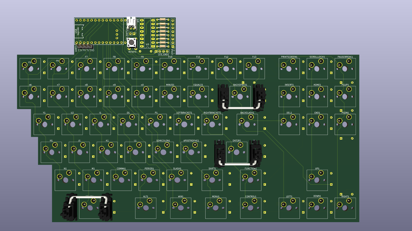
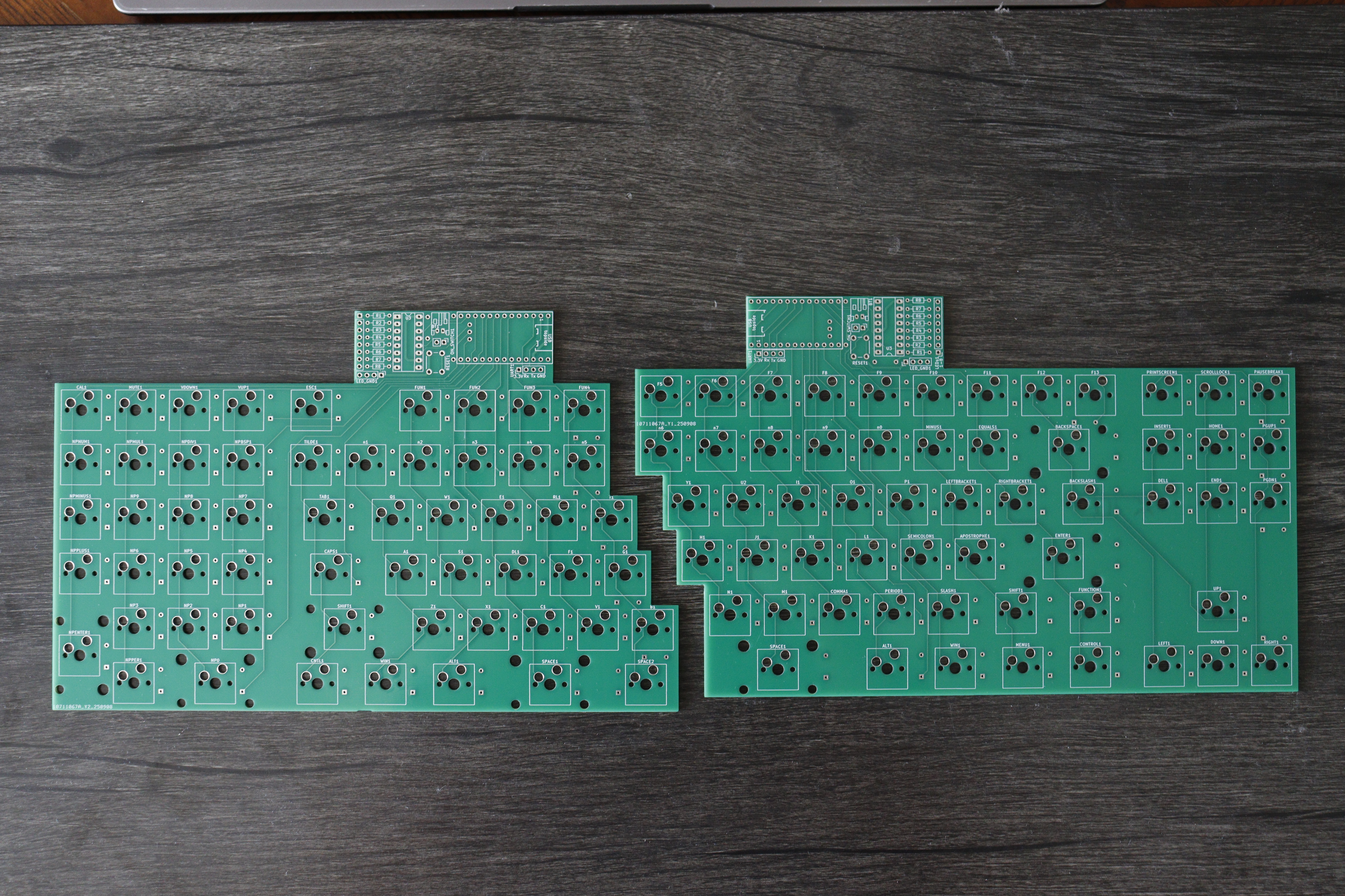
I spent the last 15 months building this split full-size mechanical keyboard. I wanted to learn PCB design, so I jumped in the deep end. I made the electrical schematics, routed the circuit boards, cut out and bent the case, soldered the components, configured the firmware, and assembled the final device.
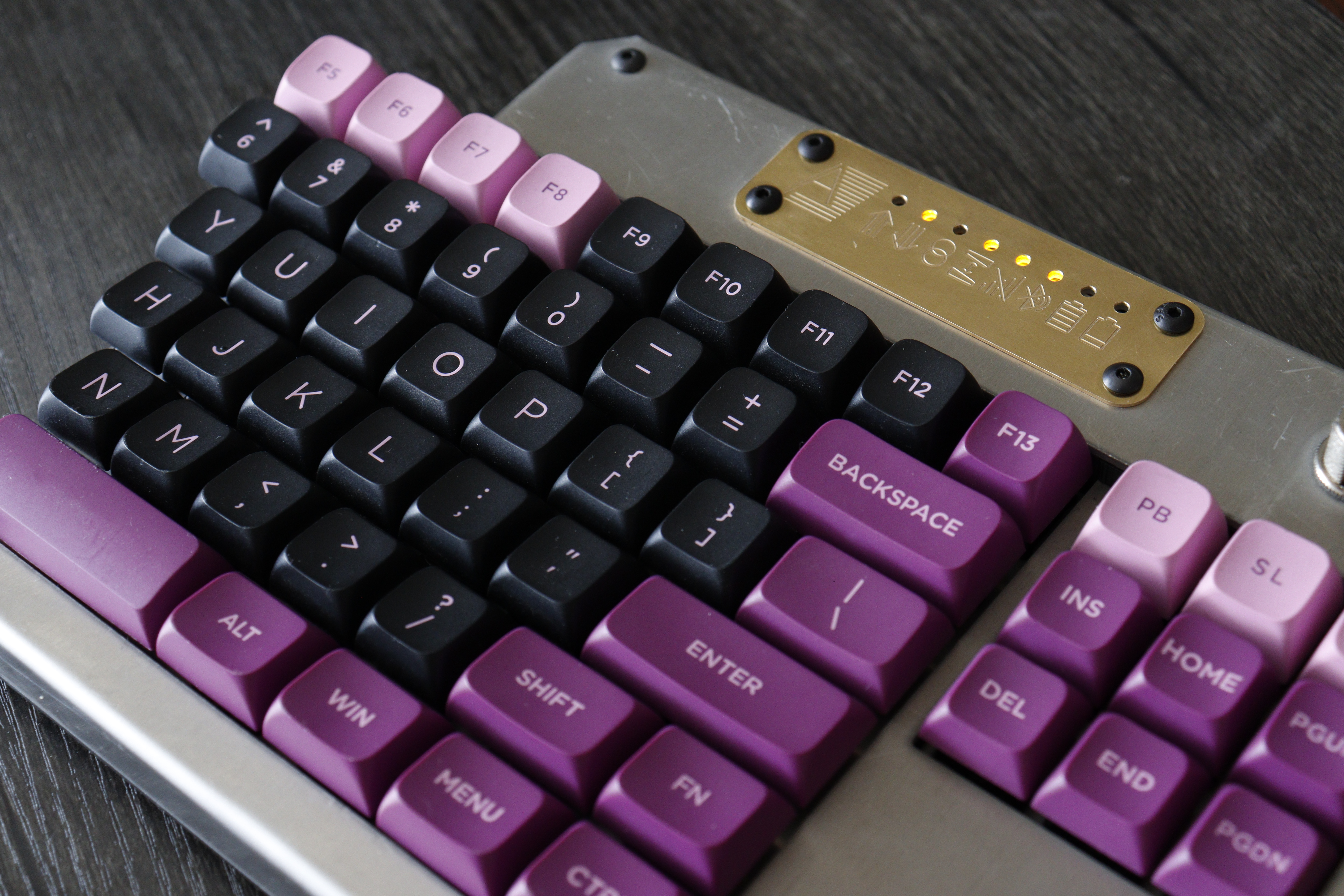
The final product has a satisfying heft to it. The metal design has a nice industrial look, especially compared to the more common 3D printed plastic.
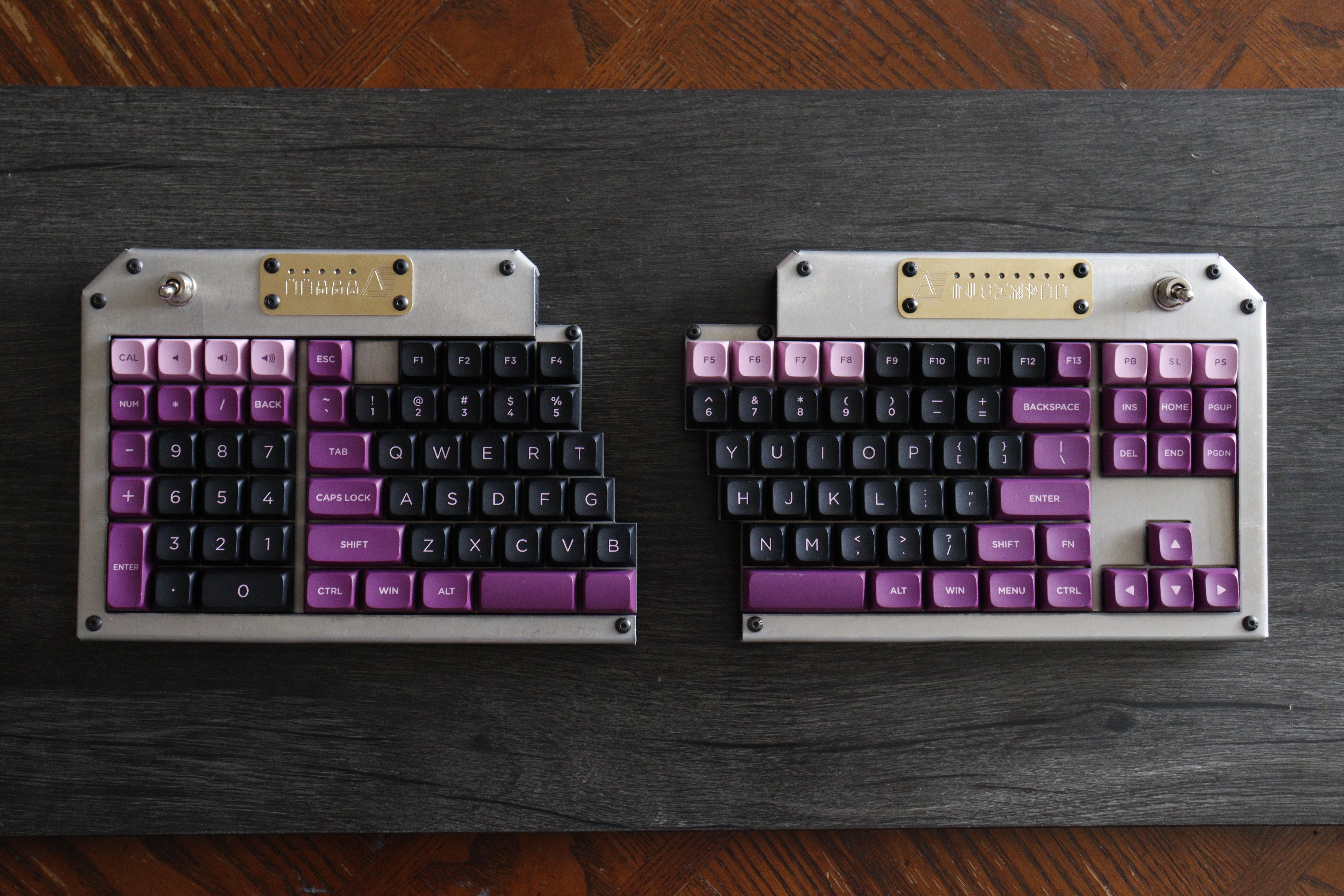
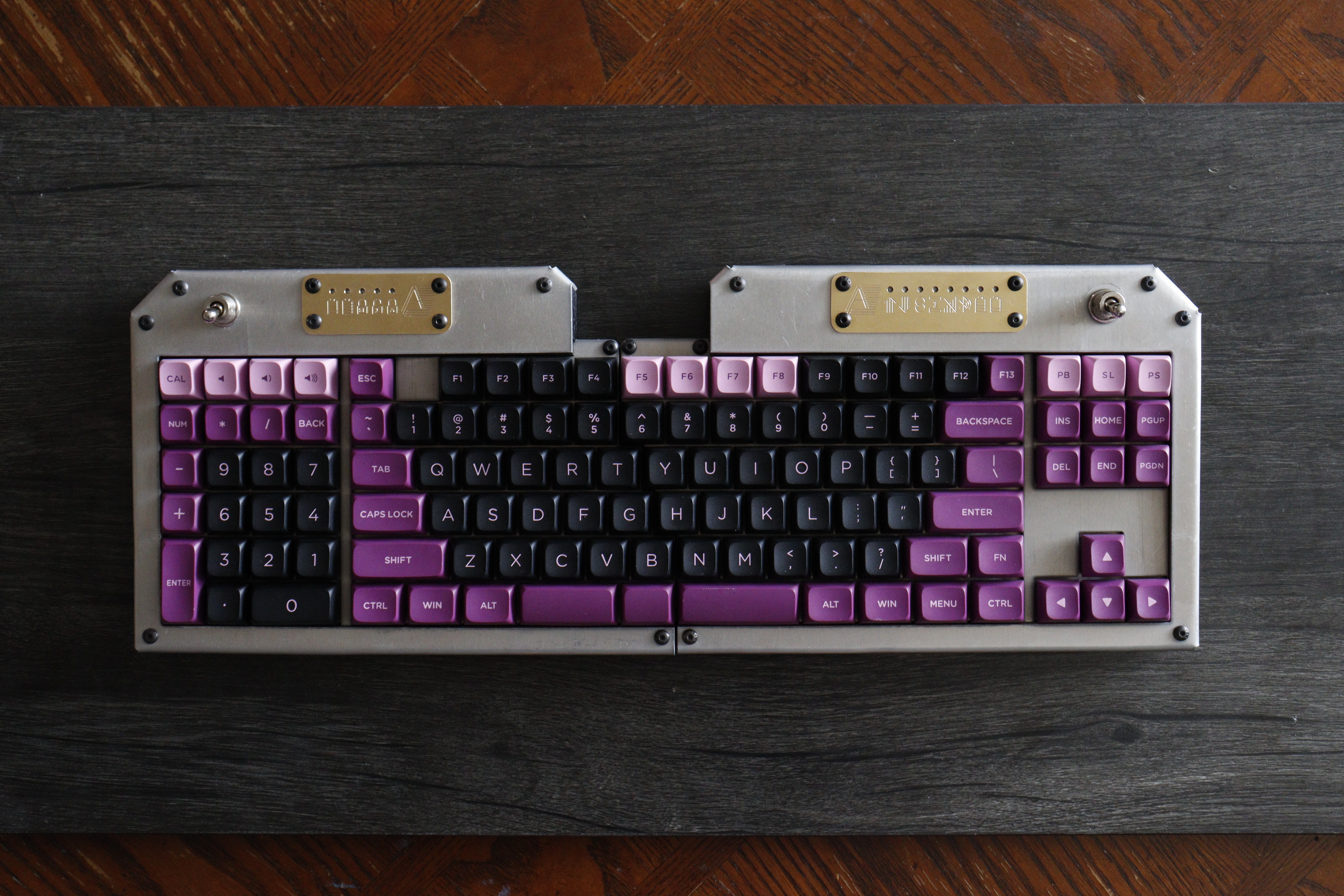
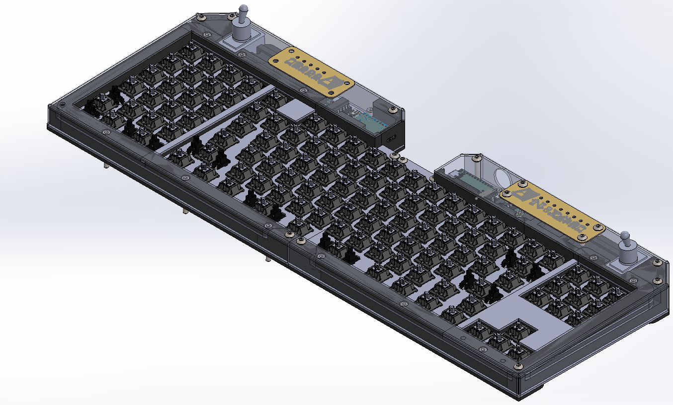
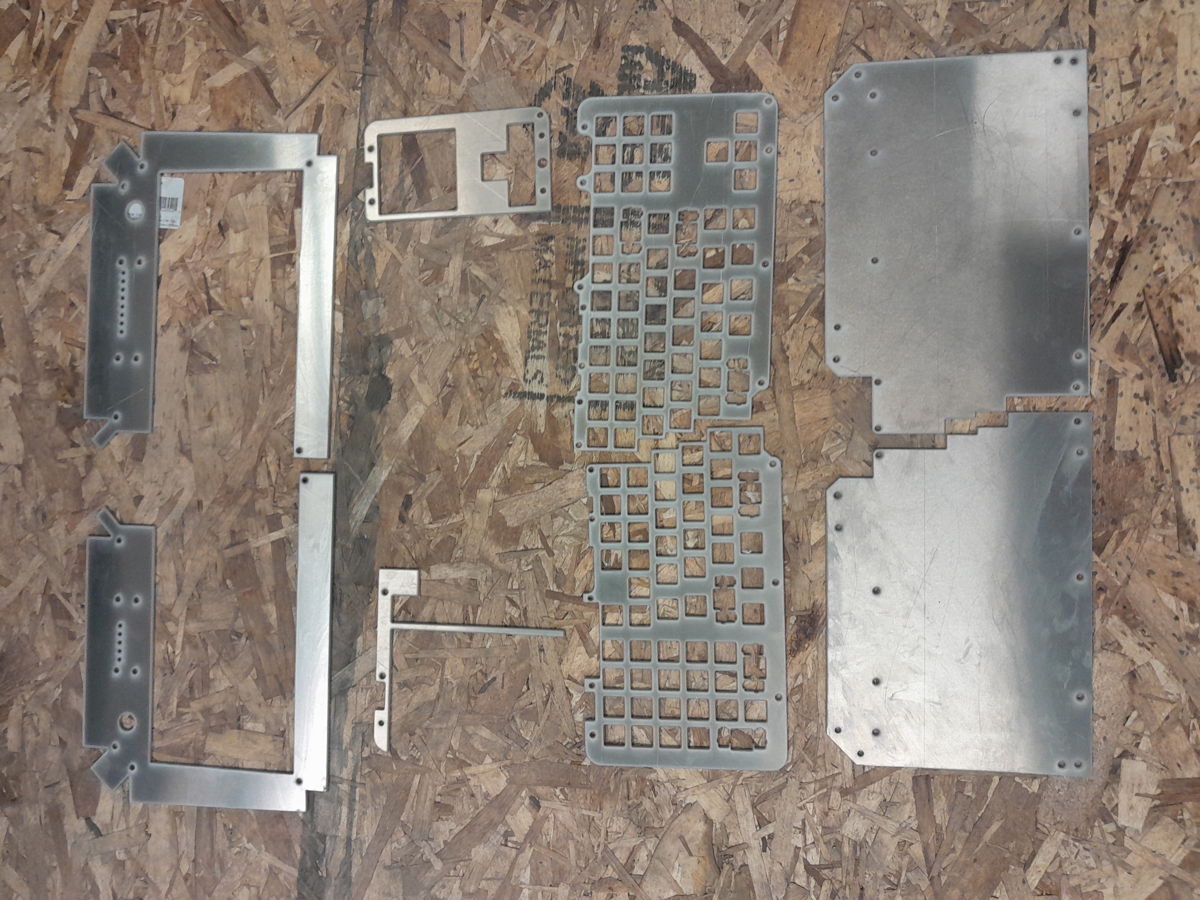
The keyboard has 113 keys and a case made from 1/16" aluminum. It's a split wireless design that runs the open-source firmware ZMK. It fits together into a full-size keyboard without extra spacing.
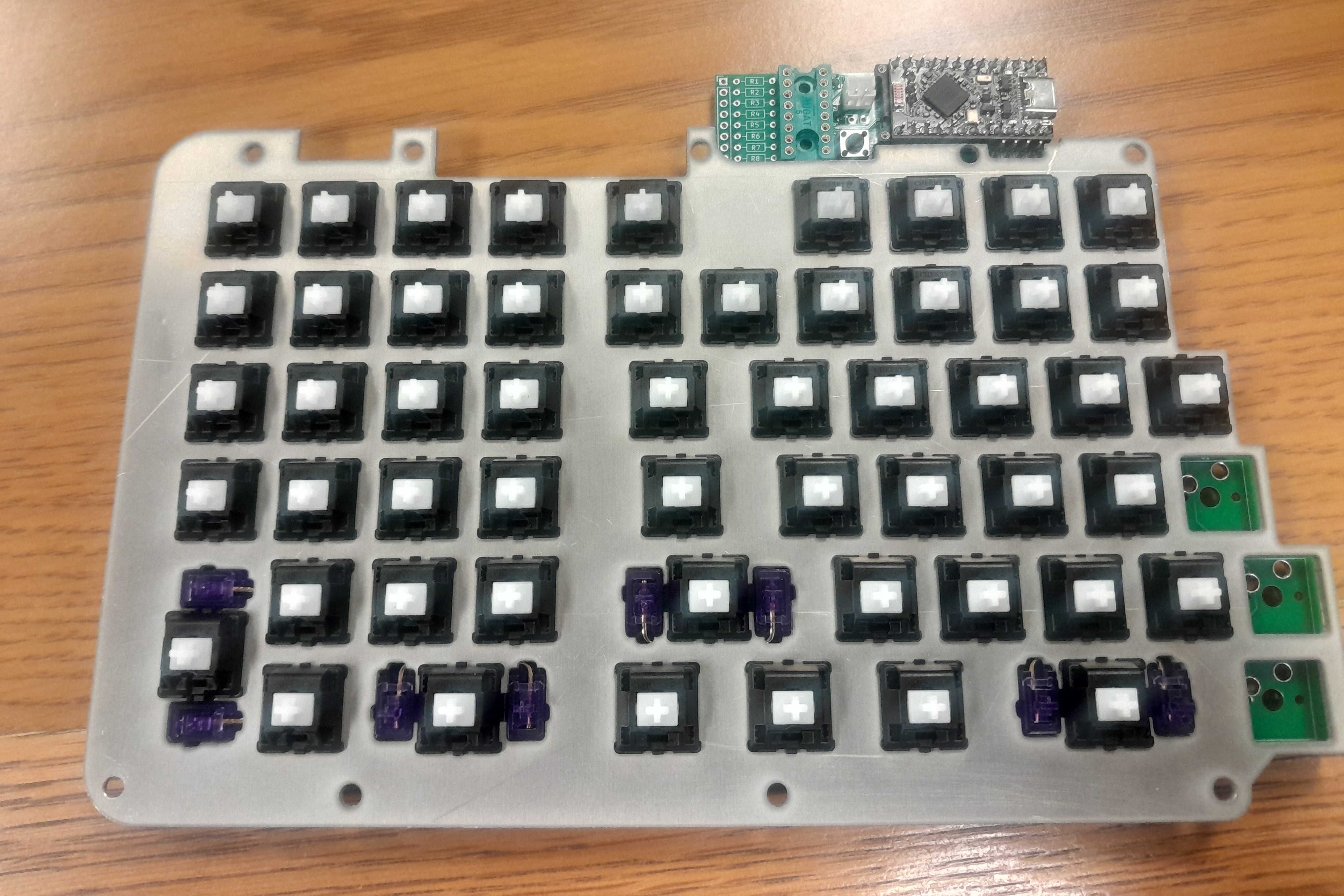
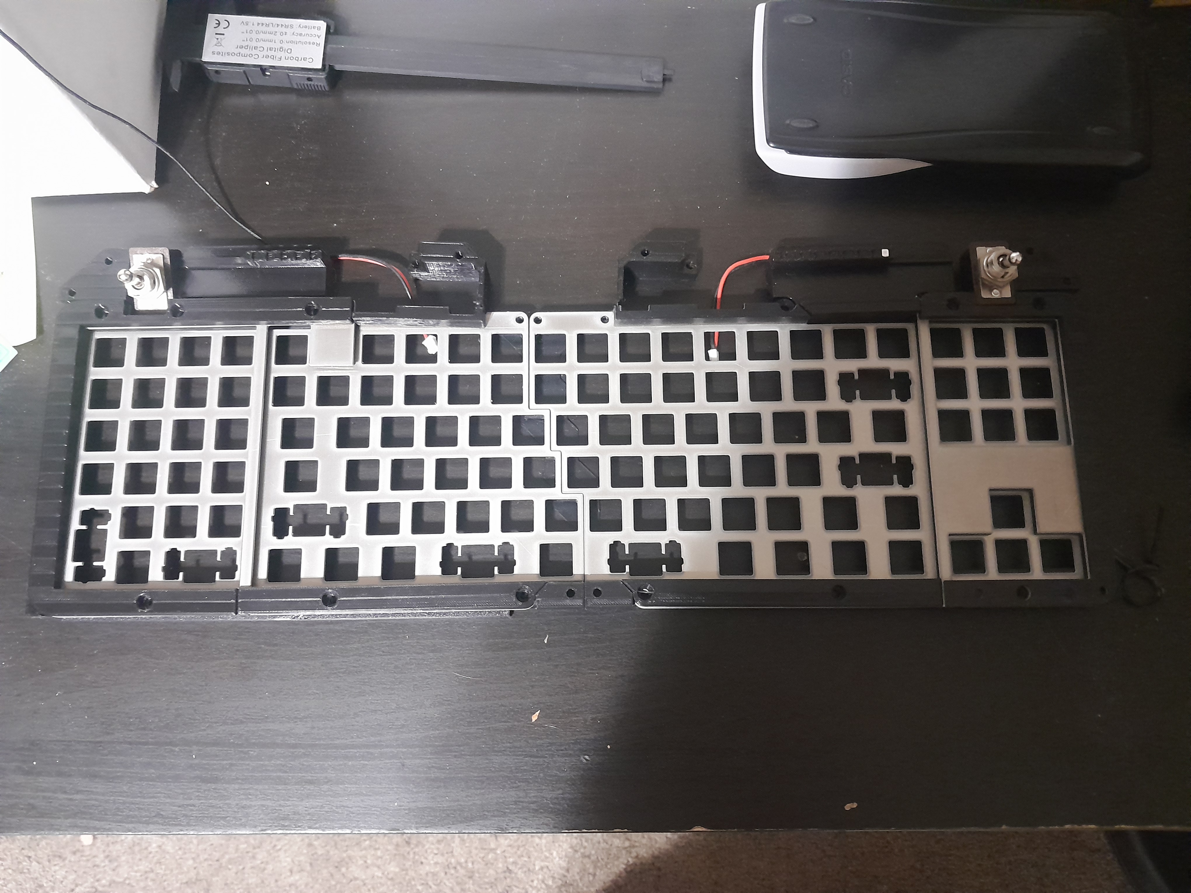
The switches are Cherry clears in hot-swap sockets. They're plate-mounted with a 2mm layer of Poron foam underneath.
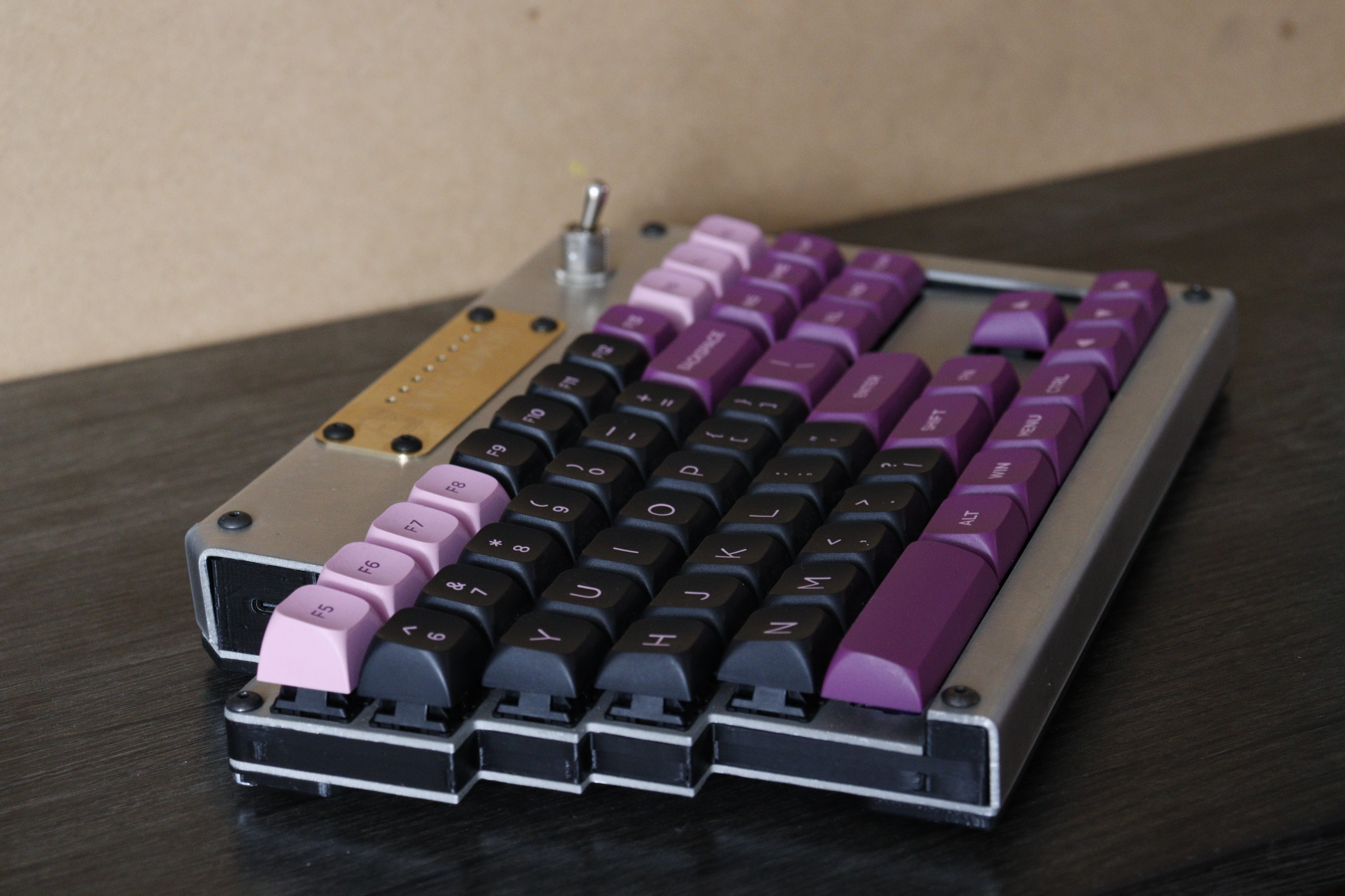
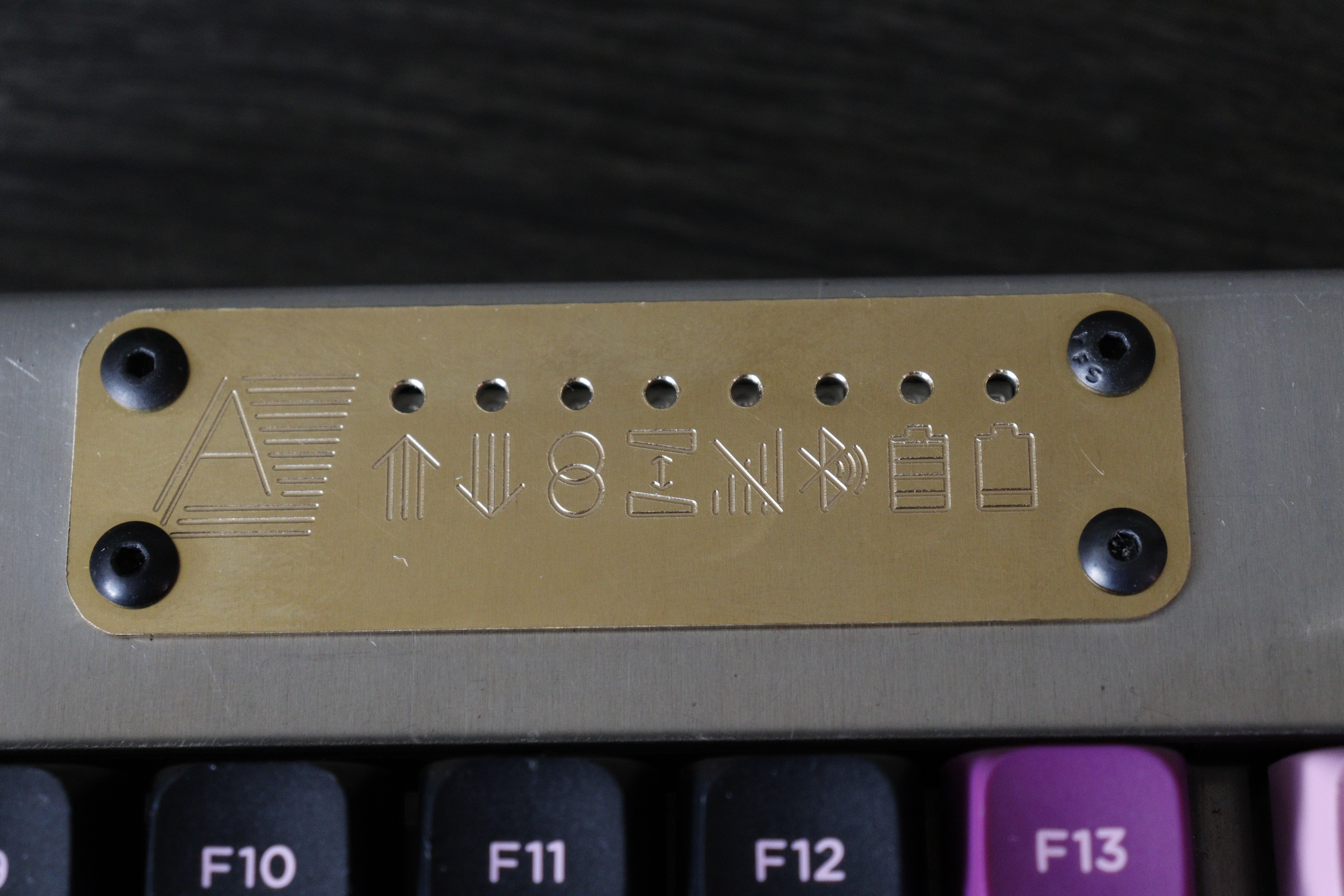
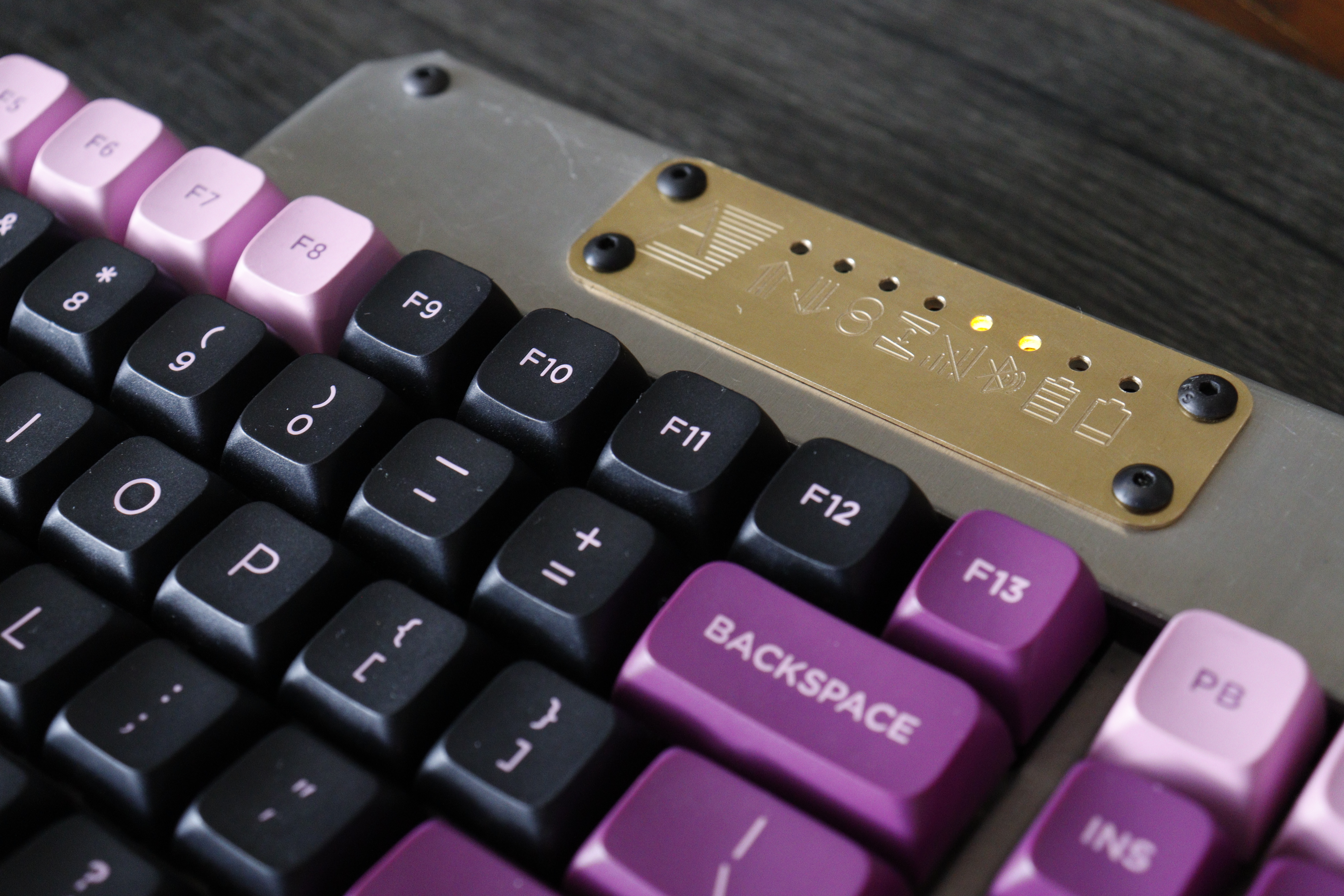
Each side is controlled by a nice!nano clone and powered by a 2000 mAh LiPo battery. The power switches are ones I had lying around. They're very clicky and quite satisfying. Each half has a row of status LEDs driven by a shift register, shining through an engraved brass plate.
When the keyboard is laying flat, the PCB is parallel to the desk. There is no tilt angle besides that provided by the keycaps. Nevertheless, the top surface of the case is angled about 1.8 degrees.
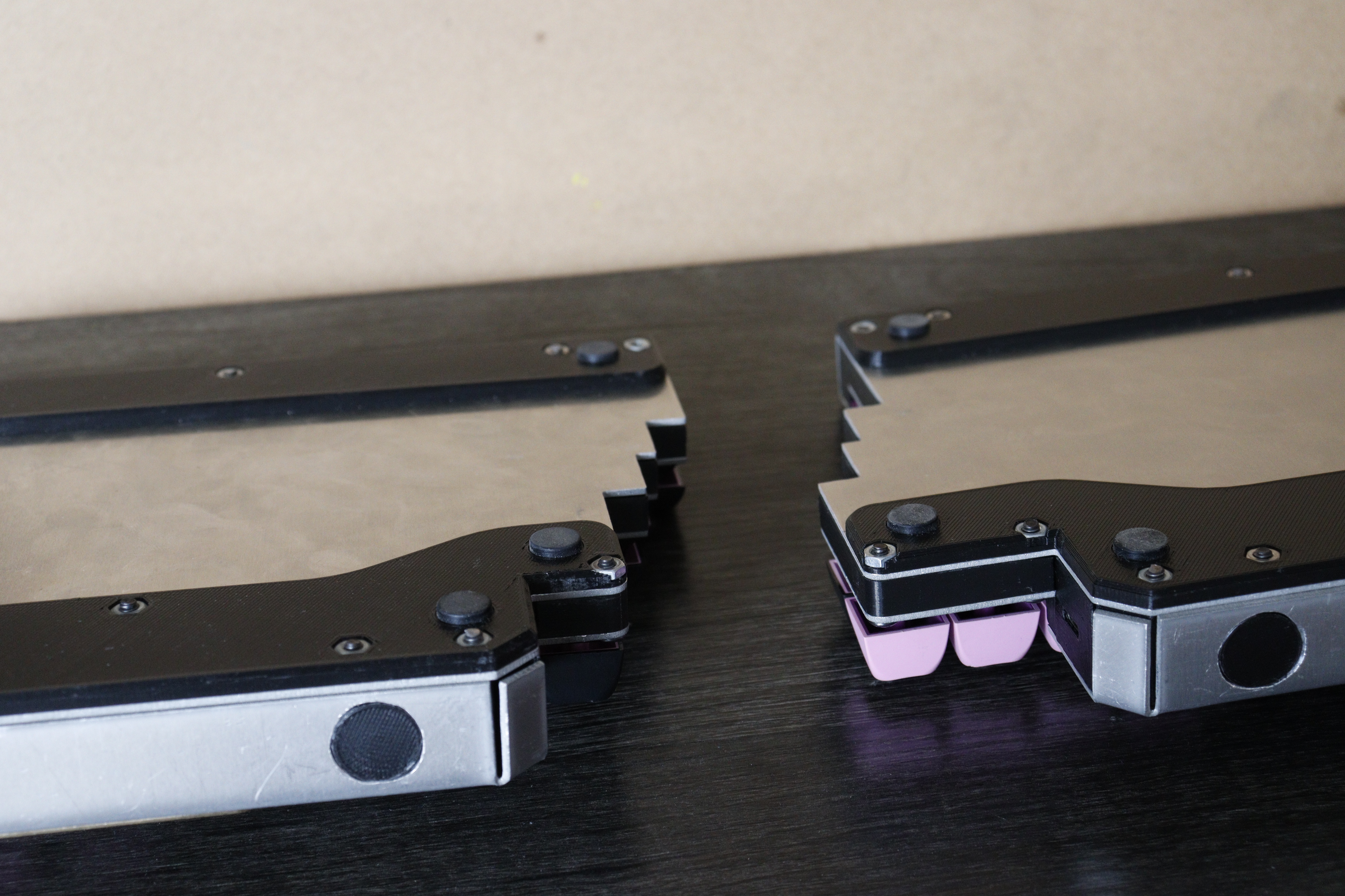
The keyboard is held together with 6-32 bolts, with nuts press-fit into the lower 3D prints.
The numpad is on the left and is mirrored from the usual layout, as I thought that would make it easier to use with my left hand. I only considered doing this because I have little to no muscle memory with numpads, usually using the number row. My goal was to make the two halves approximately the same size, and I wanted the arrow keys in their usual location.
There's an F13 key above backspace. I added this because it was in the keycap set, it made the colors better, and hey, might as well. I split the right shift key in half for two reasons: I was one small stabilizer short because I needed one for the split spacebar, and I never use the right shift when typing anyway.
The status LEDs are SMD components with wires soldered directly to them, then pressed into 3D prints. This was a terrible idea; soldering to loose parts that small was tricky.
I designed the circuit boards using KiCAD and the rest of the keyboard using SOLIDWORKS.
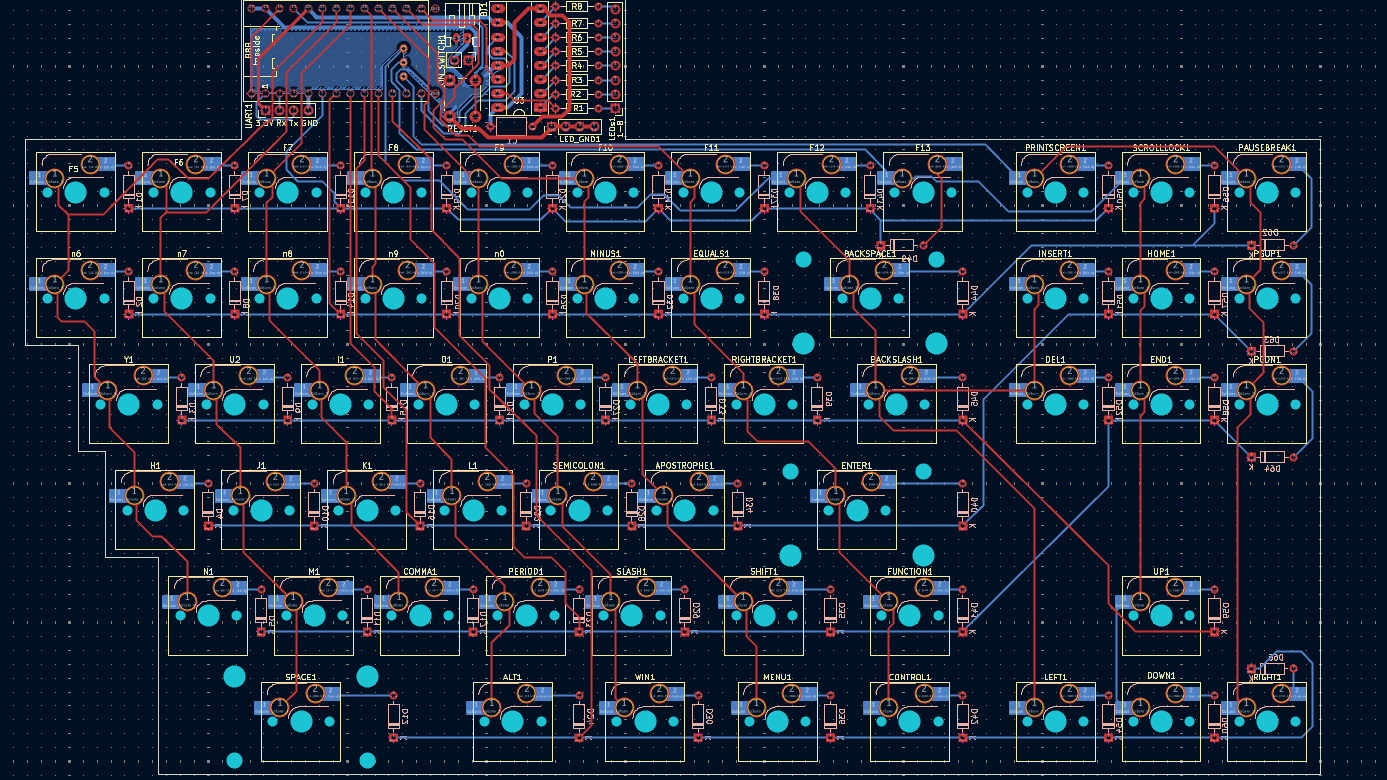
I had the PCBs made at JLCPCB. I cut out the case from 5052 aluminum using the waterjet in my university's machine shop, then bent the metal into shape. The brass nameplates were done on a CNC mill at the university shop. Most of the rest of the parts were 3D printed out of PLA.
Issues I encountered include figuring out how to connect the top and bottom parts of the case when they weren't parallel, concerns about a metal case interfering with the wireless signal, and trying to get ZMK to drive the status LEDs.
If you want more information on my build process and how I solved the problems I encountered, I kept a list of mistakes I made (and how I fixed them) that you can read here.
I used AI heavily for configuring ZMK. This did not go very well. It repeatedly told me about features that did not exist. I vibe coded the custom firmware needed to drive the LEDs. It took many attempts before it compiled, and 17 compiled versions before it worked correctly. I got much better at AI wrangling from this, but I wonder whether it would have been easier to do it myself with how much I had to dig into things.
With how long this project took me, the AI tools I was using noticably improved between my first attempts and my eventual success at getting the code running. What ultimately made the difference was getting the model to read the relevant ZMK source code from GitHub into the context window.
Thanks to:
All photos of the finished keyboard and the photo of the PCBs were done by Dallin Anderson.